:+86 15106109009
:sales@couplingzy.com

 jp
jp


The Stability of Metal Flexible Couplings in Extreme Temperature Environments
金属弾性カップリング 機械的動力伝達において独特の位置を占めています。その性能が狭い温度範囲に厳密に制限されているポリマーベースのフレキシブルカップリングとは異なり、金属弾性カップリングは、皿バネ、板バネ、ダイアフラム、ベローズ、または蛇行屈曲などの金属要素の制御された変形からコンプライアンスを引き出します。この全金属構造により、根本的な熱的利点が得られます。ただし、極端な温度では、材料特性、寸法安定性、疲労挙動、および表面状態に対して複雑で、しばしば競合する要求が課せられます。金属弾性カップリングがこれらの要求にどのように対応するかを理解することは、航空宇宙、極低温処理、鉄鋼生産、ガスタービン、および周囲条件が標準の室温設計ベースラインから大幅に逸脱するあらゆる用途で駆動システムを仕様するエンジニアにとって不可欠です。
金属弾性カップリングの定義
金属弾性カップリングは、剛性の機械的接触やポリマーインサートではなく、1 つまたは複数の金属製の柔軟な要素の弾性変形を通じて、駆動シャフトと従動シャフトの間でトルクを伝達します。弾性要素は 3 つの機能を同時に実行します。伝達されたトルクを伝達し、制御されたたわみを通じて相対的なシャフトの位置ずれに対応し、速度変動をフィルタリングして動的負荷を軽減するある程度のねじりコンプライアンスを提供します。
産業および航空宇宙分野で使用される主な金属弾性カップリング ファミリは次のとおりです。
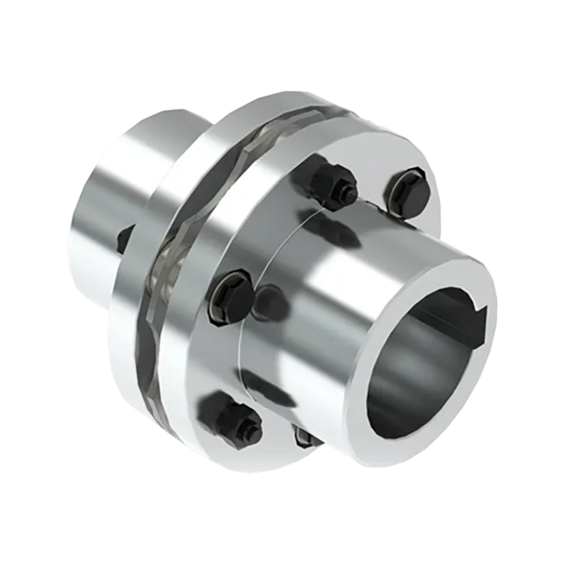
- ディスクパックカップリング: 薄い円形の積層ディスクは、通常はステンレス鋼または析出硬化合金でできており、駆動フランジと従動フランジに交互にボルト締めされています。角度および軸方向のずれに対応するため、ディスク パックにたわみが発生します。
- ダイヤフラムカップリング: 1 つまたは複数の輪郭を描いた環状ダイヤフラム。多くの場合、チタン合金または高合金鋼でできており、非常に低いバックラッシュで高トルクを伝達しながら、位置ずれに合わせて屈曲します。ターボ機械や高速コンプレッサートレインで広く使用されています。
- ベローズカップリング: 薄壁の波形金属管 (通常はオーステナイト系ステンレス鋼またはインコネル) で、軸方向および横方向に屈曲して位置ずれを補正しながら、トルク伝達のためのねじり剛性を提供します。高精度サーボおよびエンコーダアプリケーションで一般的。
- 板バネ (サーペンタイン) カップリング: 2 つのハブ フランジの間に挟まれた正弦波状または蛇行状の金属ストリップ。スプリング ストリップは負荷がかかると曲がり、ねじれに対する追従性と位置ずれの調整を実現します。
これらの設計はすべて、その性能が金属弾性要素の機械的挙動に依存するという決定的な特徴を共有しています。この依存性により、温度による材料特性の変化が極限環境用途における中心的な懸念事項となります。
金属弾性要素に対する熱の影響
温度は、いくつかの同時かつ相互作用するメカニズムを通じて、金属弾性カップリングの動作に影響を与えます。各メカニズムを個別に理解することは、広い温度範囲にわたる全体的なカップリングの安定性を評価するための前提条件です。
弾性率の変化
金属の弾性率 (線形弾性領域における応力とひずみの比) は、温度が上昇すると減少し、温度が下降すると増加します。ディスクおよびベローズカップリングに一般的に使用されるオーステナイト系ステンレス鋼の場合、500°C での弾性率は通常 15 ~ 18% 低い 室温よりも、-200°C では 10 ~ 12% 高い可能性があります。この変化はカップリングのねじれ剛性に直接影響します。20°C で規定の角剛性を実現するディスク パックまたはダイヤフラムは、高温では明らかに柔らかくなり、極低温使用ではより硬くなります。
実際の結果は、駆動システムのねじり固有振動数の変化です。システムが室温で調整され、その共振周波数が動作励起周波数から安全に離れた位置にある場合、使用温度での大きな弾性率の変化により、その共振が動作速度に近づく可能性があり、潜在的に有害な結果を招く可能性があります。 したがって、周囲温度範囲を十分に超えて動作するシステムでは、ねじり固有振動数計算の熱補正が必須となります。
熱膨張と寸法変化
金属コンポーネントは、熱膨張係数 (CTE) と経験した温度変化に比例して、加熱すると膨張し、冷却すると収縮します。金属弾性カップリングでは、これは以下に影響します。
- ボアとシャフトの適合: シャフトとハブの膨張率が異なる場合、室温でのサイズの締まりばめが高温で緩む可能性があります。これは、スチールシャフトにチタンダイアフラムハブを使用する場合など、異種金属を組み合わせる場合に重大な懸念事項となります。
- ボルト予圧: フレキシブルエレメントとそれをクランプするボルトの材質が異なり、熱膨張係数が異なる場合、熱サイクルによってボルトのプリロードが変化し、クランプ力が低下したり(トルク下でスリップする危険性がある)、あるいはフランジやディスクに応力がかかるレベルまで増加したりする可能性があります。
- 接続された機械の軸方向の位置: 長いシャフトとハウジングの熱膨張により軸方向の変位が発生し、カップリングはこれに対応する必要があります。フレキシブルエレメントの軸方向の容量は、全動作温度範囲にわたる実際の熱膨張に対して検証する必要があります。
カップリング アセンブリが大きな温度勾配にまたがる場合 (たとえば、高温のタービン シャフトを低温のギアボックスに接続するカップリング) カップリング軸に沿った熱膨張差により、持続的なアキシアル荷重が発生します トルク伝達とミスアライメント補償による動的負荷に重畳されます。
降伏強度と疲労特性
金属弾性要素の疲労寿命は、材料の耐久限界に対する周期応力振幅によって決まります。構造用金属の降伏強度と疲労耐久限界は両方とも温度に依存します。
- で 高温 、降伏強度と耐久限界が減少します。室温で快適な疲労マージンをもつように設計されたディスク パックは、意図した動作温度で材料の耐久限界に近づくか、それを超える周期応力を受ける可能性があり、耐用年数が大幅に短くなります。
- で 極低温 、ほとんどの高合金鋼とチタン合金は、引張強さと降伏強さを維持するか、わずかに向上させます。ただし、一部の材料、特に炭素鋼や特定のフェライト系ステンレス鋼は、臨界温度以下で延性から脆性への転移を起こし、その後、公称降伏強度を大幅に下回る応力レベルで破壊が発生する可能性があります。 良好な極低温靱性(最低使用温度での高いシャルピー衝撃エネルギー)を備えた材料を選択することは、低温使用におけるカップリングの基本的な設計要件です。
クリープと応力緩和
金属の絶対融点 (クリープ閾値) の約 30 ~ 40% を超える温度では、持続的な応力により、クリープとして知られるゆっくりとした時間依存の塑性変形が発生します。鋼の場合、クリープは約 400 ~ 450°C を超えると実質的に顕著になります。ニッケル超合金の場合、しきい値はかなり高くなります。
高温で動作する金属弾性カップリングでは、フレキシブル エレメントまたはクランプ ボルト内でクリープが発生し、次のような問題が発生します。 ストレス緩和 — 組み立て時に存在した弾性応力が徐々に減少します。ボルトジョイントは予圧を失う可能性があります。ディスク パックは永続的に保存される場合があります。ダイヤフラムは永続的な角度オフセットを示す場合があります。その結果、カップリングは設計通りに機能しなくなり、剛性が変化し、疲労寿命が減少し、トルク容量が低下する可能性があります。標準合金のクリープ閾値を超える用途の場合、カップリング材料は、析出硬化インコネルやワスパロイなど、耐クリープ性が実証された高温グレードから選択する必要があります。
酸化と表面劣化
酸化雰囲気中の高温では、金属弾性要素の表面に酸化スケールが形成されることがあります。ほとんどのステンレス鋼とニッケル合金では、保護付着酸化物層が形成され、さらなる酸化を制限します。ただし、熱サイクルを繰り返すと、この層が剥離して新しい金属が露出し、表面の劣化が進行する可能性があります。表面の孔食、スケールの形成、および粒界の酸化により、薄いディスクまたはベローズ要素の有効断面積が減少し、疲労亀裂を引き起こす応力集中部位として機能します。 コーティング、表面処理、または本質的に耐酸化性の合金の使用は、高温酸化環境にさらされるカップリングに対する重要な保護手段です。
高温環境における挙動
金属弾性カップリングの高温用途には、ガス タービン エンジン付属ドライブ、蒸気タービン発電機カップリング、熱間圧延機メイン ドライブ、工業炉コンベア ドライブ、石油化学コンプレッサー トレインなどがあります。これらの環境では、カップリングは 250°C から 600°C をはるかに超える温度にさらされる可能性があり、起動時と停止時に熱サイクルが重畳されます。
高温使用のための材料の選択
フレキシブル要素の材料の選択は、高温カップリングにとって最も重要な設計上の決定です。材料はいくつかの基準に基づいて評価されます。
- 析出硬化型ステンレス鋼 (17-4 PH、15-5 PH): 強度、適度な温度耐性 (約 300 ~ 350 °C まで)、および耐食性の優れた組み合わせを提供します。コンプレッサーやポンプ用途のディスクパックカップリングに広く使用されています。
- オーステナイト系ステンレス鋼 (316L、321、347): 析出硬化グレードよりも優れた耐高温酸化性があり、約 500 ~ 550℃までの強度が使用可能です。 321 および 347 安定化グレードは、高温に長時間さらされた後の感作や粒界腐食に耐性があります。
- ニッケル基超合金 (インコネル 718、ワスパロイ): 650°C 以上まで高い強度と耐クリープ性を保持します。標準のステンレス鋼では不十分な、最も要求の厳しい高温ターボ機械のカップリングに使用されます。
- チタン合金 (Ti-6Al-4V): 高い比強度と約 300°C までの優れた高温耐性を提供し、回転慣性を最小限に抑える低密度と組み合わせます。重量が制約となる航空宇宙および高速ターボ機械のダイヤフラム カップリングに適用されます。
高温時の潤滑に関する考慮事項
金属弾性カップリング are generally designed to operate without lubrication at the flexible element — the flexure is intended to be a clean elastic deformation, not a sliding contact. However, the hub bores, keyways, and fastener threads in high-temperature couplings require anti-seize compounds or high-temperature thread lubricants to prevent galling and to ensure that the coupling can be disassembled for inspection without damaging the mating surfaces. Standard molybdenum disulfide (MoS₂) paste is widely used up to approximately 450°C; copper-based anti-seize compounds extend protection to higher temperatures.
遮熱および断熱戦略
非常に高温の機械と周囲温度の機械をカップリングで接続すると、シャフトに沿った熱伝導やカップリングを通じた熱伝導により、下流のコンポーネントの温度が設計限界を超えて上昇する可能性があります。 断熱層(通常は低導電率合金の短い部分またはセラミックコーティングされたスペーサチューブ)をカップリングスペーサに組み込むことができます。 熱の流れを制限します。一部の設置では、カップリング自体を動作温度範囲内に維持するために、強制空冷または水冷カップリング ガードが使用されます。
極低温環境における挙動
Cryogenic applications for metal elastic couplings include liquid natural gas (LNG) plant compressor drives, liquid oxygen and liquid nitrogen pump drives, superconducting magnet systems, aerospace propellant pump drives, and cryogenic wind tunnel test rigs. Operating temperatures in these environments range from –50°C down to –269°C (liquid helium temperature).
Material Toughness and Ductile-to-Brittle Transition
The overriding material concern in cryogenic coupling design is fracture toughness. Carbon steels and standard ferritic stainless steels undergo a transition from ductile to brittle fracture behaviour at low temperatures. Below the transition temperature, these materials can fail suddenly at stress levels far below their nominal yield strength. Austenitic stainless steels (304L, 316L) and most nickel-base alloys do not exhibit this transition — they remain tough and ductile down to liquid helium temperatures, making them the standard material choices for cryogenic flexible elements.
Titanium alloys also retain adequate toughness at cryogenic temperatures, though they must be evaluated for hydrogen embrittlement in applications involving liquid hydrogen.
Increased Stiffness at Low Temperature
As noted above, the elastic modulus of metallic materials increases at cryogenic temperatures. A bellows or disc pack coupling that has been designed for a specific torsional stiffness at room temperature will be measurably stiffer at –196°C. This stiffness increase shifts the torsional natural frequency of the drive system upward and alters the dynamic load distribution in the system. Drive train torsional analysis should be performed at both the warm and cold operating conditions to confirm that no critical resonances are introduced across the full thermal operating range.
Thermal Contraction and Fit Management
Metallic components contract at cryogenic temperatures. For a hub bore fitted to a shaft by interference, the contraction is in the direction that increases the interference — cryogenic conditions generally tighten shaft fits rather than loosening them. However, when dissimilar metals with different coefficients of thermal expansion are combined , the differential contraction can produce very high interface stresses. Careful selection of fit dimensions and material combinations, verified by thermal stress calculations, is required to ensure that neither loosening nor yielding of the interference fit occurs across the operating temperature range.
Elimination of Lubrication Requirements
A significant operational advantage of metal elastic couplings in cryogenic service is their inherent freedom from lubrication requirements at the flexible element. Conventional grease-lubricated couplings — such as gear couplings — cannot be used in cryogenic environments because lubricants solidify at low temperatures, causing seizure. The all-metal, lubrication-free flexure of disc, diaphragm, or bellows couplings is therefore a practical necessity in many cryogenic drive applications, in addition to being a performance advantage.
Thermal Cycling: Cumulative Effects and Fatigue Interaction
Many extreme-temperature applications do not involve sustained steady-state operation at a single temperature — instead, the coupling experiences repeated thermal cycles as the system starts up from cold, reaches operating temperature, and shuts down again. Each thermal cycle superimposes a cycle of thermal stress on the existing mechanical stress state of the flexible element.
Thermal fatigue — crack initiation and propagation driven by cyclic thermal stresses — is distinct from mechanical fatigue but interacts with it. The total fatigue damage accumulated by the flexible element is the sum of contributions from mechanical load cycles (torque fluctuations, misalignment-induced bending cycles) and thermal stress cycles. In applications with frequent thermal cycling, the thermal fatigue contribution can be comparable to or greater than the mechanical fatigue contribution , and both must be included in the service life assessment.
Thermal cycling also drives progressive dimensional change through ratcheting — the accumulation of small increments of plastic deformation with each cycle — and through differential expansion and contraction of bolted joints, which can alter preload over time. Periodic re-torquing of fasteners and inspection for permanent deformation of flexible elements are therefore standard maintenance practices for couplings in thermally cyclic service.
Comparative Performance of Metal Elastic Coupling Types in Extreme Temperature Service
The table below summarises the suitability of the four principal metal elastic coupling types for high-temperature and cryogenic service, along with their key temperature-related performance characteristics.
| Coupling Type | Typical Flex Element Material | High-Temp Limit (Approx.) | Cryogenic Suitability | Lubrication at Flex Element | Primary Temperature Concern |
|---|---|---|---|---|---|
| Disc-Pack Coupling | 17-4 PH SS, 316L SS, Inconel 718 | 300–600°C (material-dependent) | Good (austenitic grades) | None required | Disc fatigue at reduced endurance limit; bolt preload loss |
| Diaphragm Coupling | Ti-6Al-4V, 15-5 PH SS, Waspaloy | 300–650°C (material-dependent) | Good (Ti alloy, austenitic SS) | None required | Creep in diaphragm at high temp; stiffness increase at low temp |
| Bellows Coupling | 316L SS, Inconel 625 | 450–600°C | Excellent (austenitic SS, Inconel) | None required | Wall thinning from oxidation; cyclic stress concentration at corrugations |
| Leaf-Spring (Serpentine) Coupling | Spring steel, 17-7 PH SS | 250–350°C | Moderate (check for brittle transition) | None required | Spring set at elevated temperature; reduced fatigue life |
Design Considerations for Extreme-Temperature Coupling Systems
Specifying a metal elastic coupling for service in a thermally challenging environment requires a structured engineering approach that extends well beyond standard room-temperature torque and misalignment calculations.
Temperature-Corrected Torsional Analysis
The torsional stiffness of the coupling and the torsional natural frequency of the complete drive train must be calculated at the actual service temperature, accounting for the modulus change of the flexible element material. If the drive system passes through a speed range during startup while the coupling is still cold, the natural frequency at cold conditions must also be checked to confirm that critical resonances are not excited during the startup transient.
Fatigue Life Assessment at Service Temperature
The cyclic stress amplitude in the flexible element must be evaluated against the endurance limit of the material at the operating temperature, not at room temperature. Published fatigue data for candidate materials at the intended service temperature should be obtained from the material supplier or from established design references. A fatigue safety factor of at least 1.5 to 2.0 on stress amplitude, referenced to the high-temperature endurance limit, is a commonly applied design criterion.
Thermal Growth and Axial Capacity Verification
The total axial displacement that the coupling must accommodate should be calculated from the thermal growth of each connected machine over its full operating temperature range. The axial capacity of the flexible element must exceed this calculated displacement with an appropriate margin. Where thermal growth is large, a floating-shaft (spacer) coupling with two flexible elements — one at each end — may be necessary to distribute the axial and angular demands between two flex planes.
Material and Fastener Compatibility
All materials in the coupling assembly — hub, flexible element, bolts, and any spacer components — should be evaluated for compatibility in the thermal environment. Particular attention should be given to:
- Coefficient of thermal expansion matching between hub and flexible element to avoid excessive differential growth at operating temperature.
- Fastener material selection to maintain adequate bolt preload across the thermal range; high-alloy bolting materials (A286, Inconel 718) are used in high-temperature applications to minimise preload loss.
- Galvanic compatibility when dissimilar metals are in contact in the presence of moisture at intermediate temperatures.
Inspection and Monitoring Strategy
金属弾性カップリング in extreme thermal service should be subject to a defined inspection protocol. Key inspection activities include:
- Visual and dimensional inspection of flexible elements at each major overhaul for signs of permanent deformation, surface cracking, oxidation damage, or corrosion.
- Non-destructive examination (dye penetrant or magnetic particle inspection for ferrous materials; fluorescent penetrant for non-ferrous) of highly stressed flexible element zones, particularly disc bolt holes and diaphragm bore transitions.
- Fastener preload verification by torque-check or bolt elongation measurement after the first thermal cycle and subsequently at defined intervals.
- Vibration signature monitoring during operation to detect changes in torsional natural frequency that may indicate altered coupling stiffness due to material degradation or permanent set.
Maintenance Practices for Thermally Demanding Applications
The service life of a metal elastic coupling in an extreme-temperature environment is strongly influenced by the quality and consistency of the maintenance programme applied to it. The following practices are recommended as part of a structured maintenance plan:
- Establish a thermal cycle log: Record the number of thermal cycles (startups and shutdowns) accumulated by each coupling in high-cycle-count applications such as gas turbine peaking units. Use this data to track accumulated fatigue consumption against the design life of the flexible element.
- Apply anti-seize compounds to all fasteners: Use a compound rated for the maximum expected service temperature. Re-apply at each disassembly to prevent galling and to ensure that fastener torque-tension relationships remain predictable.
- Verify coupling alignment at operating temperature: Where possible, check shaft alignment with the machine at its normal operating temperature, since thermal growth of casings and supports may introduce misalignment that is not present in the cold-aligned condition.
- Replace flexible elements on a condition-based or life-limited schedule: For safety-critical applications, establish a retirement life for flexible elements based on accumulated operating hours and thermal cycles, and retire them before that limit regardless of apparent condition.
- Store replacement flexible elements correctly: Disc packs, diaphragms, and bellows assemblies should be stored in dry, clean conditions free from mechanical damage. Even minor surface scratches or dents on thin flexible elements can act as fatigue initiation sites and should be cause for rejection before installation.
- Quick Links
- About
- Products
- Our Service
- News & Events
- Contact
- Products Series
- Flexible Couplings with Non-Elastic Elements
- Flexible Couplings with Metal Elastic Elements
- Flexible Couplings with Non-Metallic Elastic Elements
- Safety Coupling
- Rigid Coupling
- Contact Us
- Tel : +86 511 8572 3800 +86 511 8572 3900
- Mobile : +86 15106109009
- Email : sales@couplingzy.com
- Add:No.1 Zhongye Yingbin Avenue, Gaozi Street, Dantu Economic Development Zone, Zhenjiang City, Jiangsu Province, China.


